 | Same dimentions as Yagi #1
1/2" Schedule 40 PVC. Center to center spacing and element length remain the same, the primary difference with this style is the use of self tapping screws instead of pipe clamps to hold the elements, and the choke balun. Also, the ends of all elements were rounded with sheet metal sheers and filed smooth, removing the need to tape them.
Regarding the choke balun: The Homeing In website states, "Wrap about 7 turns of the feedline (with jacket in place) around the boom behind the reflector. (It will not work as well if you put the turns between the driven element and the reflector.)", yet the next picture shows a yagi with the choke between the director and reflector. The jury is still out on which configuration is better, or even if it is always necessary. If your antenna appears to give false angle readings, try the choke either between the driven and the reflector, or behind the reflector. If you uncover any clear benefit between one or the other, please let me know!
|
|
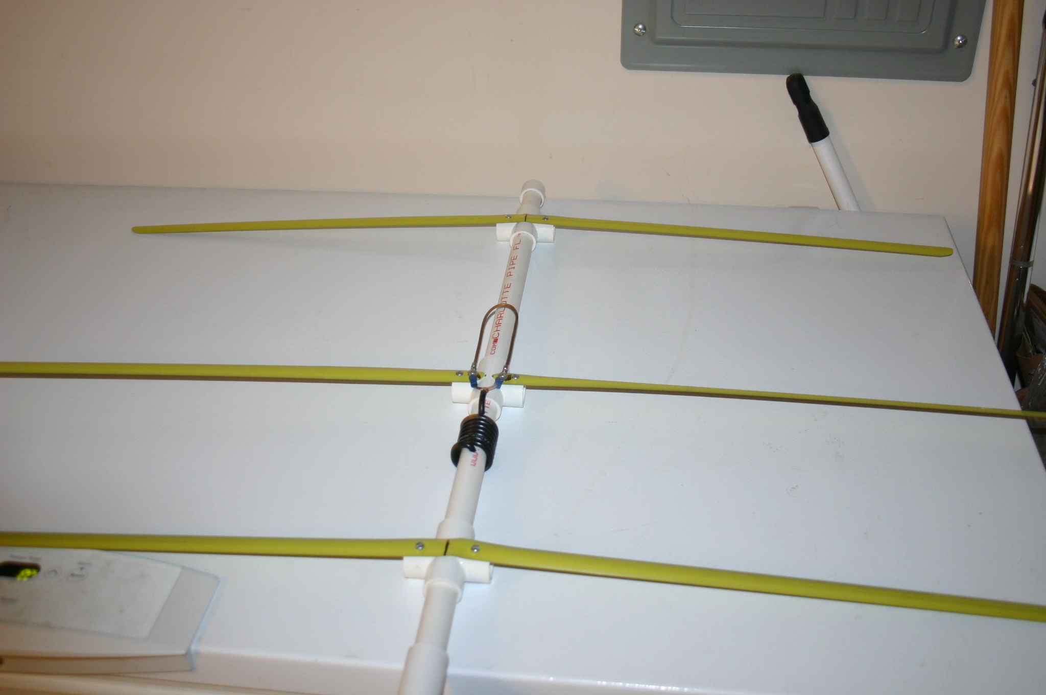
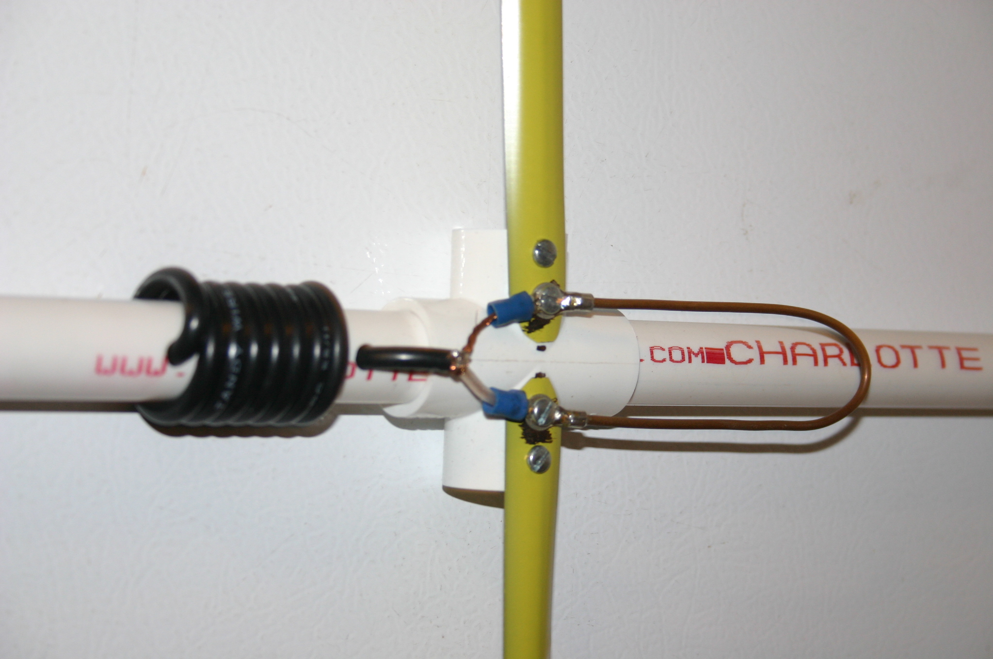 | Close up of the balun, screws, and feed line
Holes were drilled for routing the RG-58 coax through the PVC, wrapped approximately 7 turns, then back into the boom and out the back end. BNC connector was installed after the coax was routed. Lugs were soldered to the ends of the feed line and a 5.43" piece of wire bent in a loop (I used a section of ground wire from a scrap piece of 14/2 Romex©). The driven elements were sanded clean under the screws,and every thing was assembled as shown. Note the additional set of screws on the driven elements to keep them from twisting. The black dots visible on the boom at the inside tip of the driven elements are placement markers made with a permanent marker to properly set the spacing.
For the director and reflector elements, measure across the PVC 4-way and mark the center. Measure the final length of the elements and mark the center, then align the marks on the PVC and elements. Temporarily clamp them in place, drill pilot holes through the elemens and the PVC, then install the screws and remove the clamps.
|
|
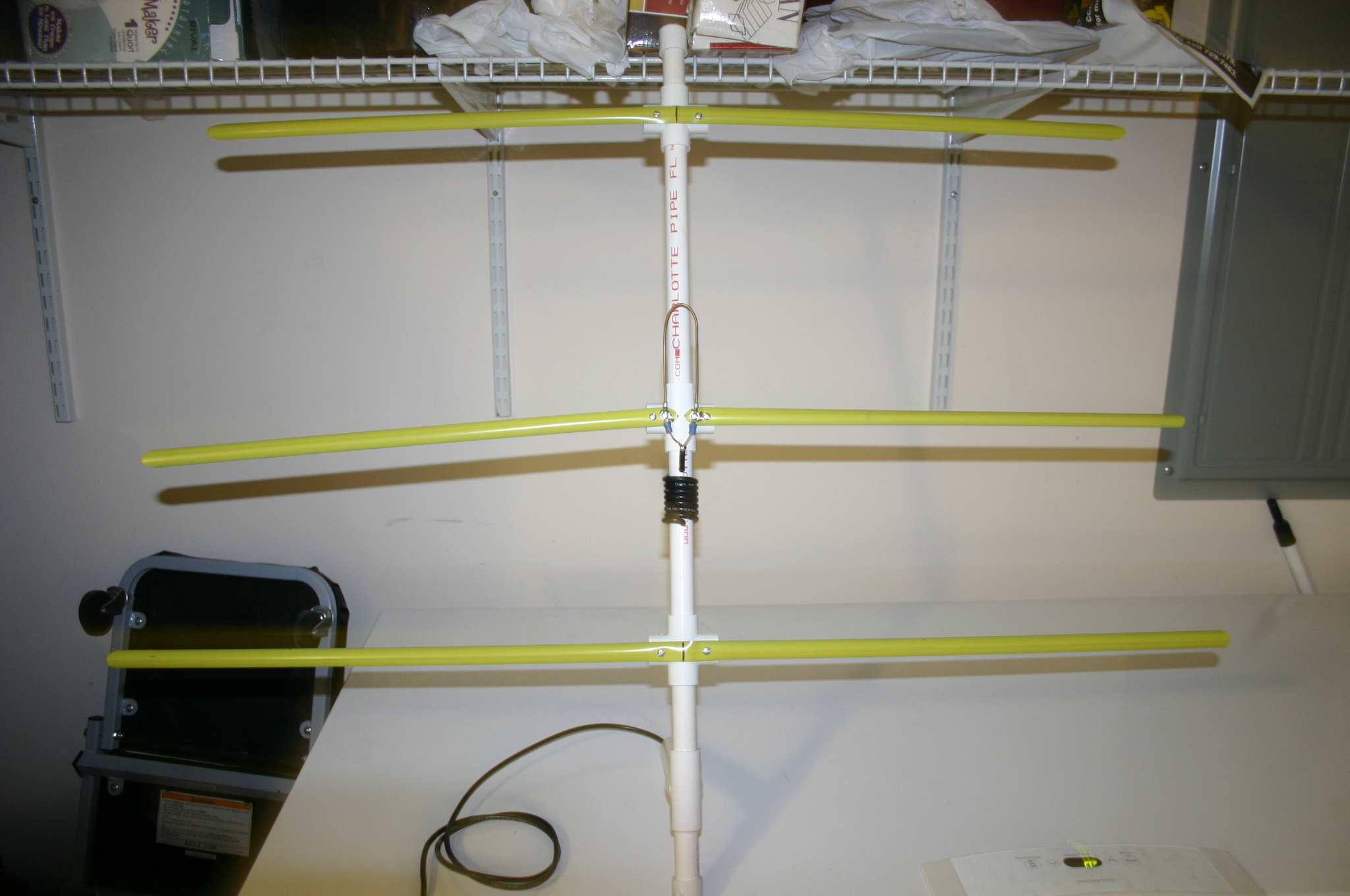 | Final assembly
Another view of the completed antenna.
Assembled and photographed by Glenn McFarlin, W4ULB
|
|