 Mobile Operations
· Mobile HF & VHF/UHF Installations
· Mobile Power Distribution
· Mobile Shack pictures - Show off your ride!
|
W4ULB Mobile Operations 2012-Present |
|
My trusty 2001 Desert Runner King Cab Frontier had done its duty and served me well, but with 210,000 miles on it and an increasing need of repairs, it was time to part ways. I loved the Frontier so I decided to buy new this time. I ended up finding a great deal on an King Cab SV model, not too fancy, but just enough comfort.
The big difference between this model and the previous was that the rear seats are mounted to the back wall. This meant I had to remove the driver side rear seat to mount my radios, but I wanted to be able to later reinstall it without any sign that things had been modified. This actually turned out to be easier than I first thought.
(Click on any picture to open a larger version) |
|
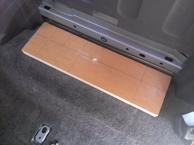
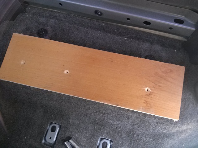
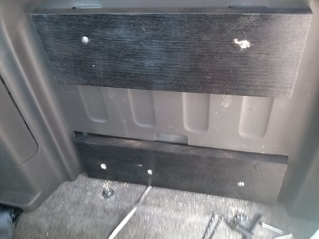
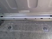
Removal of the rear seat only required unscrewing a few bolts, so it was out pretty quick. Because the seat mounts are actually recessed into the moulded facing of the rear wall, I decided to use spacer boards to allow the main plywood mounting board to fit in the same space as my 2001 installation. On one side of the lower board, prior to paining, I dug out a space for the center bolt head to recess into the wood and keep it from bowing. This bolt will be used later as a central ground point. Three holes were strategically located and drilled along the length of the board to allow attaching to the metal bracket with sheet metal screws.
|
|
|

|
|
|
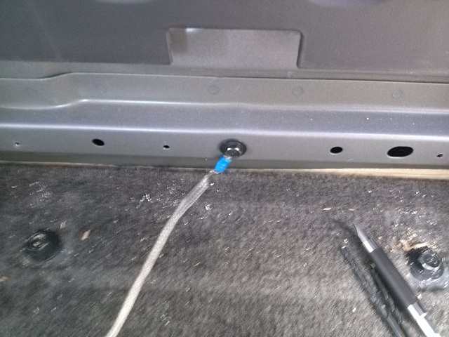
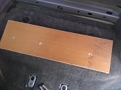
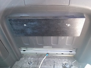
| The first picture below shows a length of ground braid with a lug crimped on one end secured under the bolt head, prior to mounding the lower board. This will become the main tie point for all the equipment ground straps. In the next photo, the top spacer board has been painted and attached. |

|
|
|
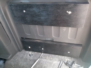
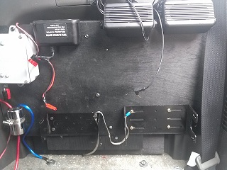
Here the ground braid has been routed under the painted lower spacer board, and the board attached.
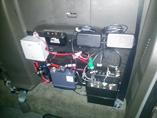
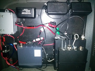
To determine best cable routing, ground points, and clearance between radios (the LDG auto-tuner was mounted to the top of the IC-706 using hook & pile strips and wire ties), the power distribution box, DC filter, radio/speaker brackets, and any items requiring through-board machine screws were laid out and mounted to the 1/4" plywood first, then the equipment board was mounted to the spacer boards. Finally, the ground braid was neatly routed and attached to each radio bracket. |
|
|
|
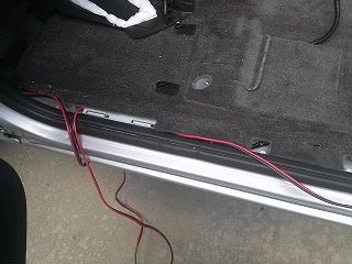
The photo on the left shows the DC line from the battery routed under the panel trim to the rear wall of the truck
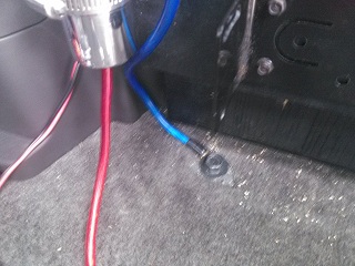
On the right is a close up of the power filter, where you can see the 2 red and 1 blue wires. On one end of the "can" is a single red wire, on the other, a red and a blue. The positive side of the main DC line from the battery goes to the single red wire, with the red wire on the other end going to the power distribution box. The blue wire is attached to one of the former seat bolts to provide a solid ground. The black wire from the main DC line goes straight to the Distribution box |
|
|
|
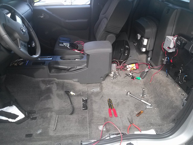
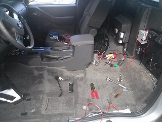
The XYL cringed when she saw my brand new truck partially dismantled. I'll have to make sure she is not around when I install the new stereo and speakers or drill the holes in the roof for the NMO mounts...
Control wires for the IC-706 and FT-8800 remote heads and CB speaker were routed from the equipment board under the carpet and center console, emerging right next to the 18" goose neck LidoMount® on the passenger side. |
|
|
| Here are several views of the final set up. It turned out even better than I though it would! |
|
|
|
|
I hope someone with a similar project finds this useful! Thanks for reading, 73 de W4ULB
|
|
|
|