|
Constructing a Tape Measure Yagi Antenna For
Hidden Transmitter Hunting
|
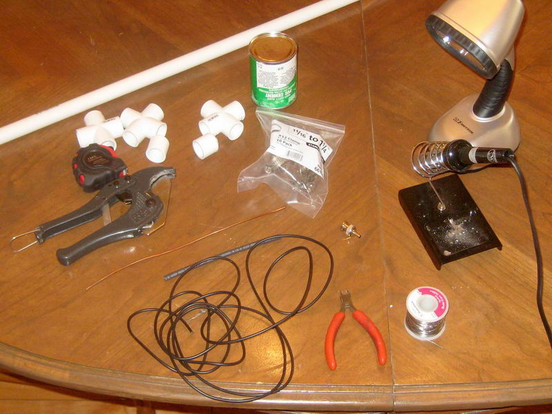
Parts List
Tools required
|
|
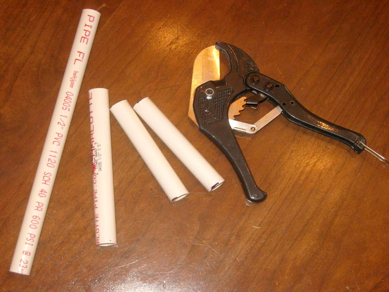
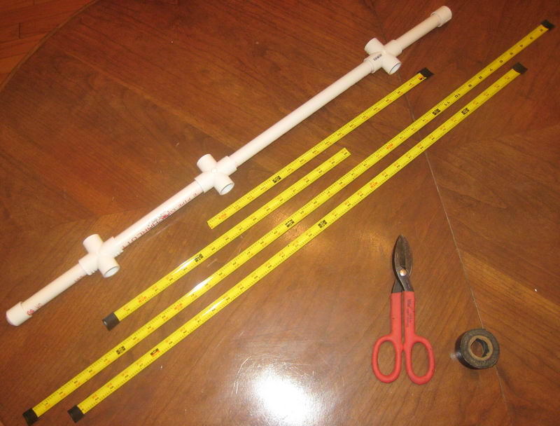
Step 1 Cut an 11 1/2 inch, a 7 inch, and two 5 inch pieces of PVC pipe. Before cutting the pipe, it might be helpful to measure and mark the length using a sharpie black marker.
|
|
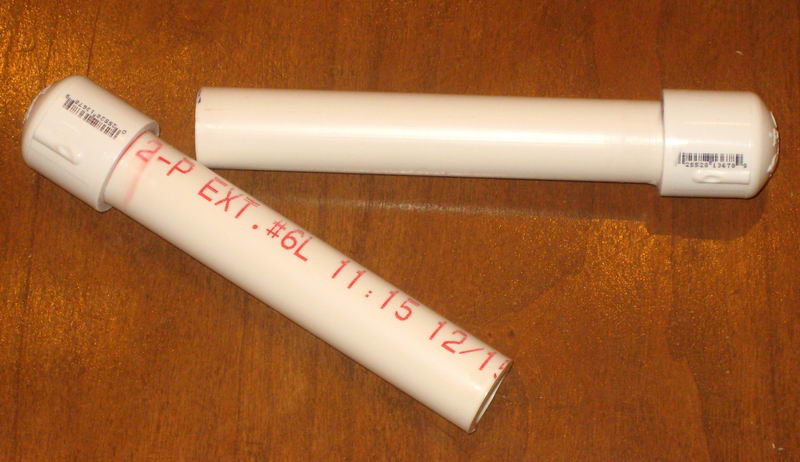
Step 2 Glue an end cap on each 5 inch (short) pipe.
|
|
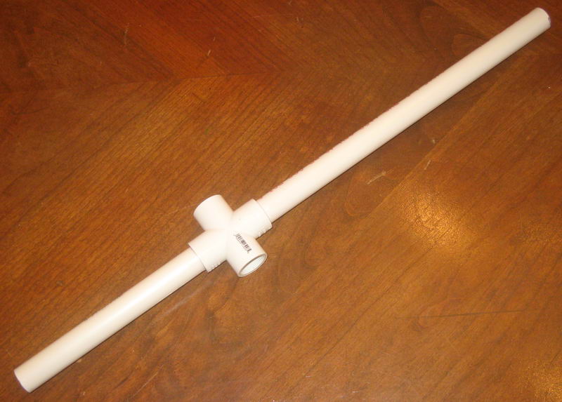
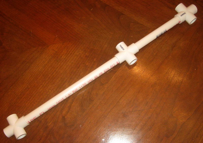
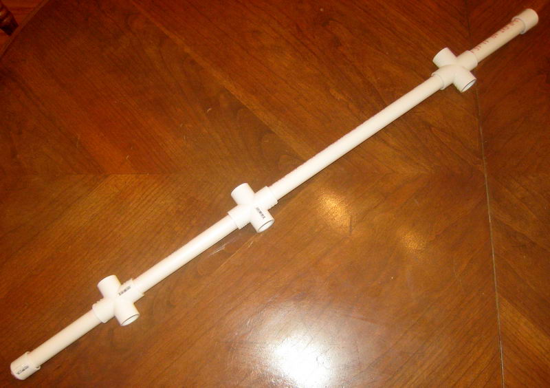
Step 3 Glue the two long pipes together using a cross connector (as pictured).
|
|
Step 4 Glue the two remaining cross connectors on to each end of the assembly from step 3. Make sure to align the cross connectors. An easy way to align the connectors is to place them on a flat surface before the glue sets and twist them to be flat with the surface.
|
|
Step 5 Glue the two short pieces with end caps to each end of the assembly from step 4.
|
|
Step 6 Cut four pieces from the inexpensive tape measure: 41 3/8 inch, 35 1/8 inch, and two lengths of 17 3/4 inchs. Be careful not to cut yourself on the sharp corners or ends. Apply short pieces of black tape on each long section, and on only one end of the two shorter pieces. This is for protection from the sharp edges.
|
|
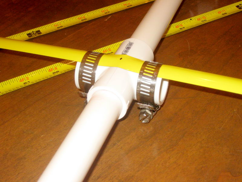
Step 7 Attach the longest (41 3/8 inchh) piece of tape rule to the cross connector closest to the center cross connector. It will be helpful to mark the center point (20 11/16 inches) with a black sharpie marker. Position the tape over the cross connector, so the curve of the tape rule is similar to the curve on the cross connector. Center and secure the element with hose clamps on each side as pictured. Attach the next longer element (35 1/8 inch) to the cross connector at the other end of the boom in a similar fashion.
|
|
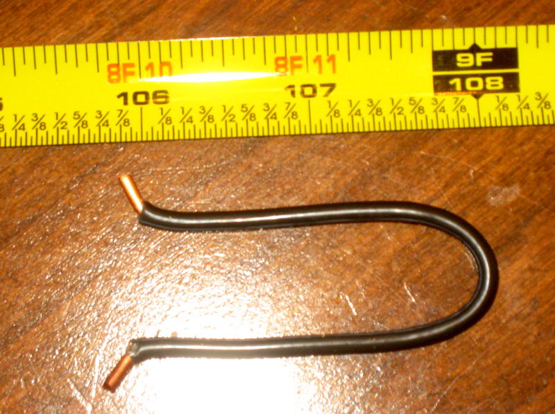
Step 8 Prepare the hairpin tuning match by bending it into a "U" shape about 3/4 inch wide and tinning the ends of the wire.
|
|
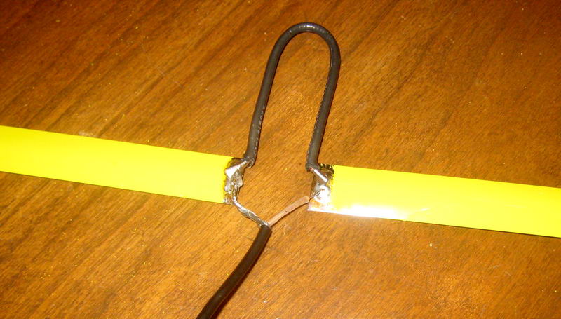
Step 10 Scrape about 1/4 inch of paint off of the two remaining pieces of tape rule from the untaped ends. Tin the bare areas, then attach the hairpin match and coax wire.
|
|
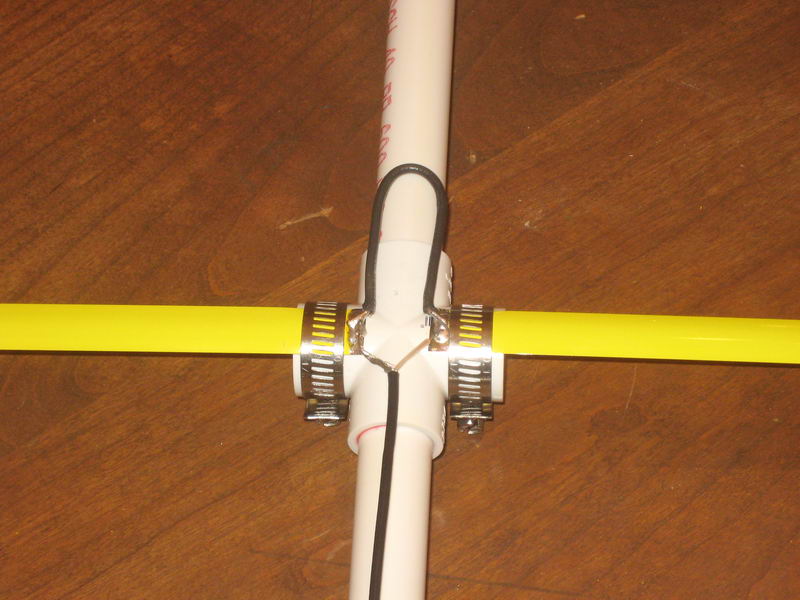
Step 11 Next attach this assembly to the boom using two hose clamps (as pictured below).
|
|
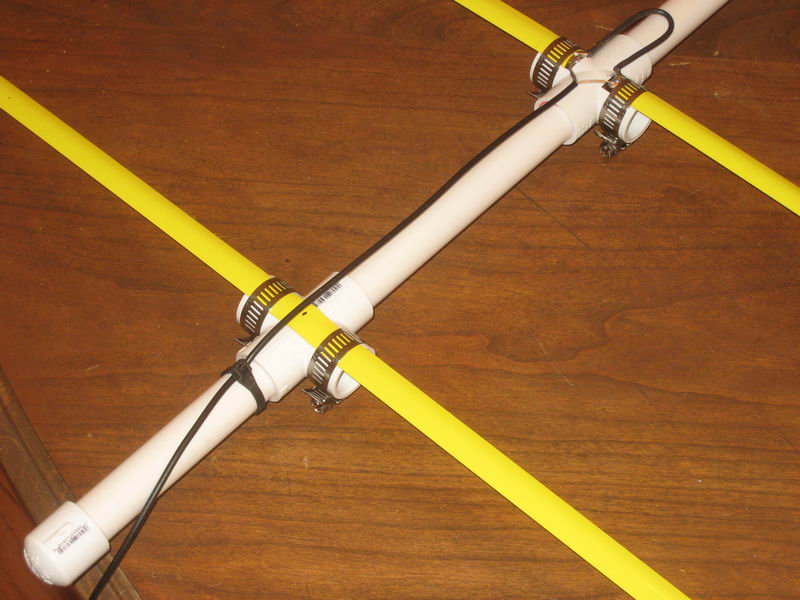
Step 12 Secure the coax wire to the boom with a zip tie or black tape. The antenna is now ready to use.
|
|
|
|
Construction plan written
and photographed by Tom Niderost, K4TMN |